Designing for the Wind
Using Dynamic Wind Analysis and Protective Stow Strategies to Lower Solar Tracker Lifetime Costs
By Alex Roedel and Stuart Upfill-Brown
Root Causes of Solar PV Claims
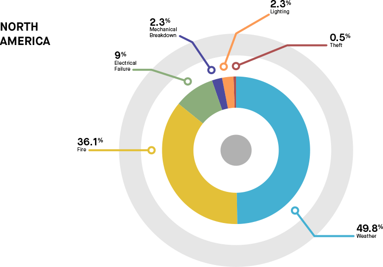
As solar deployment expands into new, highly competitive markets, utility-scale developers and owners often prioritize low upfront pricing. These downward price pressures have led some single-axis solar tracker companies to forgo the necessary engineering analyses required to properly understand the lifetime cost of their system, leading to a spike in insurance claims. A recent report highlighting rising insurance claims resulting from inclement weather (along with rise of extreme weather caused by global warming) notes that nearly 50% of solar power plant insurance claims are weather related (see Figure 1).1
As developers and owners assess the expected long-term ownership costs of their systems, close attention should be paid to whether tracker suppliers perform advanced dynamic wind analyses for their trackers--a critical ingredient in helping to accurately predict the required operations and maintenance (O&M) costs of the plant. This paper addresses the importance and challenges of comprehensive wind engineering, presents examples of pioneering wind tunnel analysis conducted by CPP Wind Engineering and NEXTracker, and provides suggestions and recommendations for solar developers, EPCs and owners to consider when they are choosing their tracker supplier.
Shortcomings of Code-Based Design
When determining design loads, most solar asset owners and developers, in addition to Authorities Having Jurisdiction (AHJs), will require a code-based design. Yet solar trackers are not accurately represented in most structural codes. In the American Society of Civil Engineers (ASCE) code, the closest representative structure is the mono-sloped roof. But this standard has several shortcomings and using it grossly oversimplifies the analysis needed for wind loading on solar tracker structures. Wind analysis of tracker solutions has shown that aspect ratio (width relative to length), varying tributary areas, and sheltering effects of surrounding rows are not covered properly by structural codes. For example, common building codes today do not take into account a 40-meter long span (typical of trackers) fixed at one end that rotates around a central point. Most importantly, the code describes static loads only and does not account for dynamic amplification effects.
In one striking example, the ASCE 7 code suggests that dynamic wind analysis may be foregone if the frequency of the structure is greater than 1 Hz. However, wind researchers have known for years that frequencies as high as 8 Hz can still cause significant dynamic loading for these light structures.
Static Wind Tunnel Testing
As the solar industry is relatively new, it is imperative to select third-party wind tunnel testing (WTT) firms judiciously, since wind tunnel testing remains as much art as science and many do not fully understand the challenges. Furthermore, code-compliant wind tunnel testing of each tracking system is crucial because it is the most accurate form of loading analysis for PV structures.
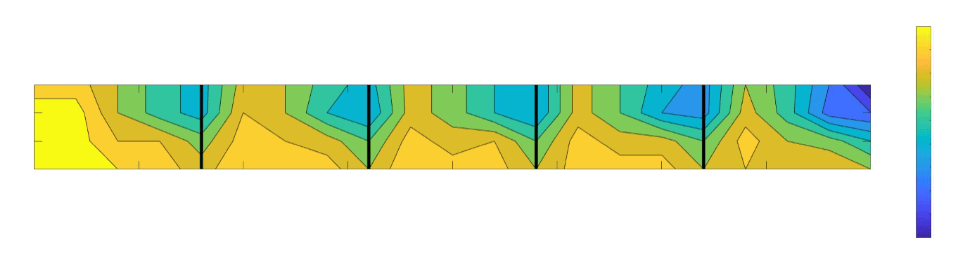
Figure 2 shows the results of a wind tunnel test, where scaled trackers are placed within a wind tunnel with sensors mounted on the models to capture the pressures from all wind directions and tracker angles. From a static loading perspective, this test shows the gust coefficient (GCN) values for the exact PV structure to be used in power plants. The test also enables the manufacturer to understand the loading across panels within a tracker row and the sheltering effect of trackers adjacent to it. This data is critical since designers must pay attention to tracker rows with east-west and north-south exposures within a power plant.
While a static wind tunnel analysis was the standard for solar engineering 10 years ago, tracker architectures and weather conditions have changed significantly. For instance, we know that dynamic wind loads during instability can exceed five times that of static wind loads. Based on failures in the field and published research, it’s clear that dynamic analysis must be included in the evaluation of all solar system designs and structures.
Dynamic Wind Analysis
While the static analysis provided by wind tunnel tests is important, the analysis of the dynamic effects of wind on PV trackers is even more critical. One area of aeroelastic instability concern is torsional galloping, in which wind vortices shed off both edges of a tracker row, causing rapid escalation of instability, which only stops when the wind stops blowing. These vortices make the tracker rotate and can rapidly amplify, causing the tracker to fully rotate through its entire tracking range and triggering large torsional loads and potential catastrophic failure.
Site-specific analysis from historical wind data at multiple sites shows that the frequency of lower wind speeds required for torsional galloping does not necessarily correlate to the tracker’s design wind speed. Table I summarizes the occurrence rate for torsional gallop-inducing wind speeds and associated failure rates for a tracker that implements a stow strategy and significant damping compared with one that is stowed flat with only basic structural damping.
| Location | 300-year Design Wind Speed (mph) | Torional Galloping Wind Potential | Average Annual Probability (%) of Winds >20mph. E-W Direction | Percent Tracker Failure in 25-year Design Life | ||
| Average Events/Year | Average Hours/Years | Stow at High Tilt with Supplemental Damping | Stow Flat with Only Structural Damping | |||
| Central CA | 120 | 41 | 188.8 | 71.1 | 1.7 | 7.4 |
| Utah | 105 | 14 | 23.4 | 6.8 | 2.7 | 14.6 |
| Saudi Arabia | 115 | 5 | 17.3 | 14.7 | 0.1 | 1.0 |
A secondary dynamic effect is vortex lock-in3, which occurs at higher tracker angles when the wind vortices hit downwind tracker rows at their resonant frequency. If the magnitude of vortex lock-in is great enough, the system can transition into torsional galloping, possibly resulting in failure. However, vortex lock-in requires wind gusts of a longer duration and, unlike torsional galloping, can be mitigated with proper damping and frequency analysis.
Research shows that the best way to combat tracker instability is through stow angles and proper damping. The computational fluid dynamic (CFD) analyses shown in Videos 1 and 2 compare stowing at 0 degrees to stowing at a higher tilt angle. At 0 degrees, the tracker will shed vortices on both sides of a panel, leading to instability. At the high stow angles, vortices will shed only on one side of the panel, better enabling a tracker to stay under control, even at high wind speeds. The precise angle and damping required varies by tracker geometry and stiffness. The CFD data, while illustrative of the root cause of the instability, has its limitations; it cannot predict the exact onset of the event as it fails to account for the full three-dimensional participation of the tracker row.
The best way to counteract torsional instability is to stow at high angles. Although this approach increases static loading on a tracker, it makes the system stable even during high wind gusts. Videos 1 and 2 show a comparison using CFD analysis, in which a high-angle stow performs well under the same wind load, while stowing at 0 degrees causes torsional galloping across a module. The torsional galloping will be even more significant for trackers that use a two-in-portrait architecture because of the squared effect of torque loads. The ideal stow angle should take into consideration tracker stow speed, row-to-row spacing and module requirements.
Instability at 0 Degrees (CFD).
Stability at High Angle Tilt (CFD).
The wind tunnel testing captured in Video 3 shows the stowing of a tracker at 0 degrees; as the wind speed increases, the tracker model goes into torsional galloping. Once previously attributed to resonance, the research proves that the phenomenon is a separate issue. Video 4 shows the effect is relatively steady when the tracker model is set at a certain stow angle. The test mentioned above was then replicated in a multi-row wind tunnel test shown in Video 5, which illustrates the instability of a flat plate as wind speed increases. Note that there is no level of damping that can reverse torsional instability. The wind or load input must actually stop. Recent videos posted on social media also show this happening in the field to trackers that do not properly account for the dynamic effects of wind in their designs, leading to the significant damage to PV plants, huge insurance claims and extended system downtime.
Instability at low-angle tilt and no added damping (WTT).
Stability at high-angle tilt with damper (WTT).
CPP has written a seminal paper4 on these studies demonstrating the effects of torsional instability on flat plate panels. This behavior has been observed for years yet it has not been fully understood until recently, through research by NEXTracker and CPP.
Multi-Row Test of Instability at 0 Degrees (WTT).
Stow Angles: High Beats Low
Stowing flat has been the industry standard until recent years, since it is the best way to combat static loads at high wind speeds. However, dynamic analysis demonstrates that 0 degree or flat stow is the most dangerous position a flat plate panel can be held in during a wind event. Many EPCs and owners have witnessed catastrophic failures caused by stowing their trackers at 0 degrees, so they often attempt to protect themselves by creating a higher design wind speed. However, such efforts will not prevent torsional instability from happening. CPP researchers have discovered that even at low wind speeds of 25 m/s (~90 kph, or 55 mph), this instability will occur for stow angles 20 degrees and below.
Go To Stow Without UPS
When storms cause power outages in the vicinity of a solar power plant, this can leave PV trackers vulnerable during wind events if they are unable to go to a safe stow position. Much of the industry relies on an expensive uninterrupted power source (UPS) to move the trackers to stow position, but this approach ultimately causes another potential point of failure since many systems may reside between the UPS and the tracker controllers. NEXTracker systems rely on battery-backed controllers that will go to stow without relying on power from the grid, ultimately protecting the tracker and module assets in an effective and safe manner.
Tracker Architectures
Many engineering companies design single-axis trackers for the design wind speed (~145-195 kph, or 90-120 mph) with an assumption that the tracker remains stable up to that point. Research at CPP has shown that instability occurs well below the design wind speed if not properly accounted for in the design. There are several characteristics at play in tracker dynamics.
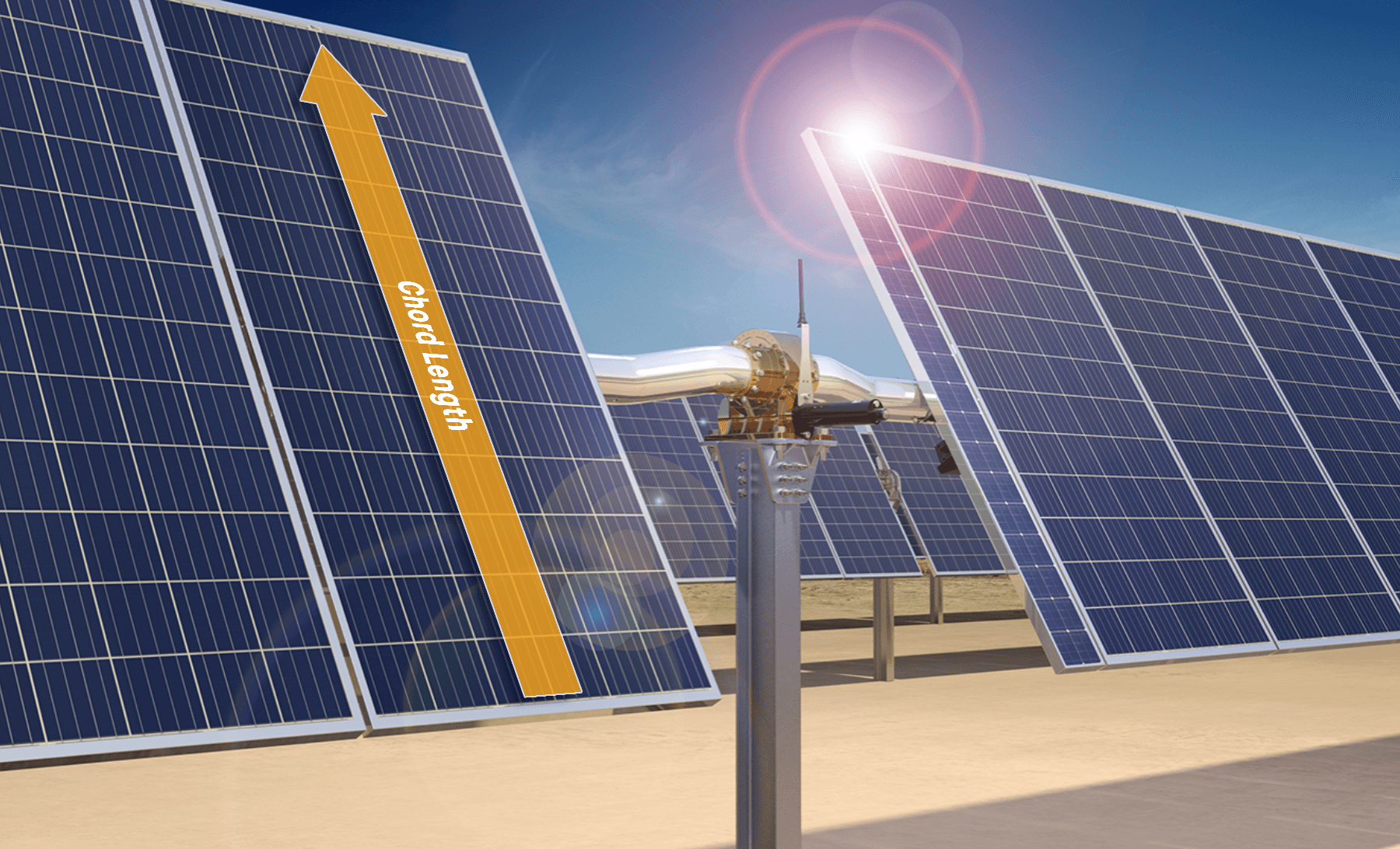
The first characteristic is chord length. When stowed parallel to the ground, chord length refers to the east-west length of a single tracker row (see Figure 3). Conservatively assuming consistent design coefficients, the torque in the system increases with the square of the chord length, while increasing linearly with the length of the row.
The second is resonant frequency, a characteristic based on several elements of tracker design, including weight, length and stiffness. One tracker row will have several dynamic mode shapes and a resonant frequency for each. These resonant frequencies can be used to form a basic understanding of the magnitude of wind speeds that will cause dynamic amplification.
The third characteristic is damping. Dampers reduce oscillations of a tracker when the tracker sustains dynamic effects under wind loads. Research shows that damping can sufficiently limit the effects of vortex lock-in but will not prevent a tracker from going unstable when stowed near 0 degrees. Torsional damping increases the energy required to excite the system and most mechanical damping is below 5%, falling short of the threshold required to sufficiently damp the dynamic response of the tracker, particularly vortex lock-in. In other words, some method of damping beyond the structural damping is required to arrest the dynamic motion of the tracker. Finite element analysis (FEA) on modal shapes can be used to determine a dynamic amplification factor (DAF) for certain damping ratios (see Figure 4). Beyond this, field testing must be done to validate the results. A properly damped system greatly reduces the likelihood of failures in the field when paired with the proper stow strategy.
The fourth characteristic is wind stow parameters and performance, which has been discussed earlier in the paper. It’s important that the control software chooses the correct stow angle and that the system itself can move quickly to the safe position.
Large-chord, low-stiffness tracking solutions are becoming more commonplace as these provide several perceived advantages, including greater power density and fewer foundations than other designs. However, wind analyses that go beyond the shortcomings of code-based design reveal that these initial advantages must be weighed against the increased risk of dynamic failure in several modes. While we have highlighted two of the more troublesome dynamic excitations, particularly those related to torsional modes of vibration, responsible designers must also account for higher vibrational modes. Those modes involving bouncing/heaving motions of the tracker are particularly susceptible to vortex shedding from upwind rows.
Wind Testing and Analysis Recommendations
Based on best practices that we have developed and implemented, NEXTracker makes the following recommendations for solar tracker wind testing and analysis:
A properly conducted static wind load test must take place, with both exterior and interior rows modeled. The array tested should contain enough rows to capture the true reduction of wind loads in the array interior and the dynamic effects on downwind rows caused by vortex shedding. The testing should encompass different tilts, wind approach angles, row spacings and torque tube heights as intended for field installations. Owners should require that wind tunnel testing be peer reviewed by competent wind engineering experts to check for the veracity of loads obtained.
A wake buffeting–based dynamic analysis to capture elevated loads caused by vortex shedding in the array interior should also be required. A field pluck test or an impact hammer test followed by system identification analysis to ascertain the modes of vibration and structural damping in the system will inform the parameters of the wake buffeting study.
A preliminary CFD analysis (single or multi-row) for torsional instability is needed to get the range of critical wind speeds related to this instability. This will provide a parametric analysis of the effect of stiffness, damping and stow tilt on the instability trigger.
Finally, a full 3D, multi-row aeroelastic study to capture the effect of torsional galloping and vortex lock-in is strongly recommended, along with ways to minimize the instability response in terms of design modifications and/or stow strategy adaptation.
Site-Specific Analysis
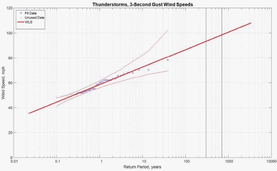
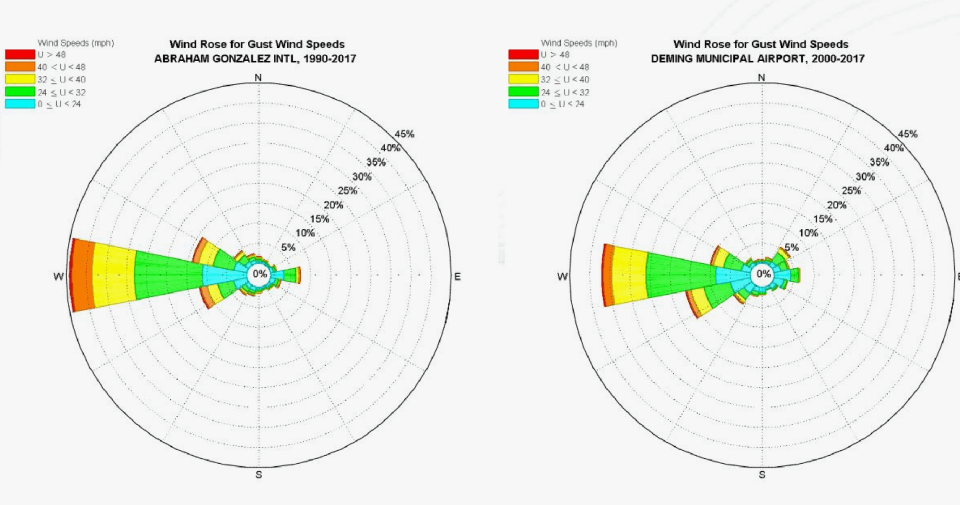
In addition to comprehensive CFD analysis and wind tunnel testing, attention must be paid to how the wind behaves at project sites. Each large solar installation has a unique set of wind conditions that need to be factored into site design and layout. NEXTracker has worked with CPP to determine site-specific wind climate analysis on many sites in the U.S., Mexico, Australia and elsewhere, using local weather station data to assess the precise locations of wind speeds rather than simply measuring wind speeds over large regions. Factors such as wind speed, direction and frequency are analyzed to create site-specific calculations and determinations for suitable design wind speeds (shown in Figure 5) and directionality (shown in Figure 6).
Importance of Robust Reliability and Quality Practices
Of course, no amount of wind testing and analysis will overcome a less-than-robust quality and reliability program. The ongoing quality process implemented at NEXTracker and throughout our supply chain incorporates vendor and product verification, quality assurance program, ongoing production monitoring and statistical process control, reliability testing initiatives, field reactivity and support, and continuous improvement through Six Sigma methodology. NEXTracker uses these wind studies not only to inform design of the stowing parameters, but also to determine reliability and performance standards for key parts of the system such as dampers and drive components.
As a result of the combination of our work in dynamic wind analysis and our rigorous quality and reliability processes, NEXTracker has experienced a significant reduction of wind-related failures in the field. Thanks to the research indicating the need to stow our trackers at high wind angles, our systems have survived direct hits by hurricanes, monsoons and other extreme weather events, coming back online quickly without failures after the storms have passed. The video in Video 6 shows NX Horizon™ trackers successfully riding out a storm.
A Key Wind-Mitigation Component: Fasteners
A key but often overlooked aspect of tracking system structural integrity and reliability comes down to a basic component—the fastener. The majority of NEXTracker fasteners are permanently "swaged" (a type of non-torqued fastening), a sturdy design requiring little or no maintenance.5 NEXTracker uses highly durable, permanent fasteners that do not loosen over time, eliminating the need for periodic torque checking. No oils or lubricants are required in the maintenance of the system, as all motors and gears are sealed. Because the fasteners rely on tension between the components rather than torque to stay firmly in place, they are far less likely than regular nuts and bolts to come loose or become damaged during the dynamic vibrational stresses experienced by the system during a wind event.
A Note on Module Types, Frames and Wind
Another important consideration for the long-term durability of a tracker system is the integrity of the module-to-tracker interface. As illustrated earlier, the dynamic excitation of the tracker structure during moderate wind events can govern the design of the structure−in many cases more so than the static wind pressures during the maximum design wind event per traditional building code. Even properly damped, aeroelastically stable trackers will experience small deflections and vibrations of the structure during moderate wind events. This reality has important implications on design for reliability of the module-to-tracker attachment.
Advantage of Framed Modules
Framed modules distribute the loading generated by wind pressure evenly across the perimeter of the module glass and into the aluminum module frame, providing better support for this brittle glass. This prevents the occurrence of excessive load concentration on any specific area of the module glass. This even-load distribution across the glass also applies to the vibrational and dynamic forces transmitted through the tracker structure during wind vibrations.
Framed modules also allow for a relatively short mounting span across the long side of the PV module frame. NEXTracker uses a 400-mm span. This places the module mounting points close to the centerline of the torque tube, so that relative movement between the module frame and tracker is minimal.
Risks of Frame-Less Modules
Unframed modules apply the loads generated by wind pressure into four small contact patches located at the module glass perimeter. These contact patches are typically mounting clamps approximately 15 mm wide and 150 mm long, resulting in highly concentrated forces in a small area. While the concentration of stress may not be an issue during industry-standard static load testing, it is important to consider the additional stress caused by structural deflections and vibrations during wind events, which can exceed those experienced in a simple static load test.
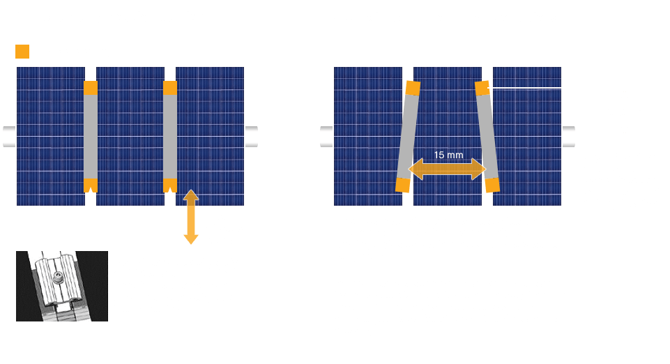
Since unframed modules do not benefit from the continuous glass support provided by the module frame, they must also be supported at a much wider span, typically around 1200 mm. Unlike a framed design which features positive mechanical engagement, attachment to the module laminate is made with rubberized clamps that rely solely on friction to secure the PV panel. During wind vibrations, the relative movement between the tracker structure plus the long cantilevered mounting rails and the module glass laminates will be much greater than the framed design. This is because the 1200 mm module mounting points are much further away from the torque tube centerline. For example, a relatively minor rail deflection of only 1.5° will result in a 15 mm lateral displacement at the module mounting clip on a 1x portrait tracker. For a 2x portrait tracker, this deflection will be nearly double. Most unframed module attachments use 15 mm of total clamping engagement, relying on friction only. In summary, there is significant risk of module slippage out of the rubberized clamps during wind events.
As mentioned previously, frameless panels provide little surface area around the perimeter for mounting; typically, only 15 mm of clamping depth is available between the cell edge and laminate edge. This limits the design options for mounting rails, which can cause edge-shading losses when used with bifacial modules. Increased rail depths are required to achieve sufficient strength to support the module loads at the 1200 mm locations, which are cantilevered 600 mm away from the torque tube center. The required rail depth may be as much as 150 mm, which causes substantial rear-side shading of the edge cells in a bifacial application.
Until recently, nearly all modules installed on trackers included full perimeter frames. We believe that framed modules will continue to be the lowest LCOE solution for tracking systems when considering capital expenditures (module + tracker + installation labor + installation breakage) and the impact of long-term operating expenditures on module slippage and breakage. We expect this LCOE advantage for framed modules to be even greater for bifacial technology. If unframed modules are selected for use on a tracker, owners and independent engineers should apply a more-stringent qualification process because of the considerations listed above. If these considerations are ignored, the expenses incurred from unframed module damage will be borne by the long-term system owner.
Regarding the long-term durability of a tracker system and the module-to-tracker interface, NEXTracker recommends testing for the following criteria before qualifying any tracker system for use with frameless panels:
- Static load testing.
- Cyclic load testing.
- Vibration testing: the effect of wind vibrations on module slippage or cracking; frequencies should be determined based on aeroelastic wind tunnel analysis.
- Tracker movement testing: the effect of tracker east-west rotation on module slippage.
- Rubber clamp endurance testing: UV exposure and mechanical relaxation.
DNV Bankability Study
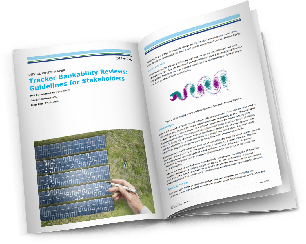
The industry has stepped up its efforts to ensure the quality and reliability of solar trackers. A recently published white paper by independent engineering firm DNV GL, “Tracker Bankability Reviews: Guidelines for Stakeholders,” lays out a detailed outline of best practices for the IE community for performing unbiased technology evaluations of single-axis trackers.6 The DNV publication reinforces many of the recommendations made in this white paper, underscoring the necessity of thorough structural validation and analysis as well as the imperative for both static and dynamic wind tunnel testing.
Additional Considerations
When looking at trackers and any other equipment, it is imperative that designers and owners understand the value and sustainability of the company standing behind the offer. In addition to the comprehensive wind testing, analysis, and stow strategy discussed in this document, other key O&M considerations should include parts availability, service technician’s time on site, remote bidirectional monitoring, and proactive reporting. NEXTracker has found that the long-term cost of ownership for system owners can be significantly reduced with proper digital connectivity. By having a proactive, intelligent software-based approach, service and O&M teams know strategically when a repair or replacement is required to minimize any potential downtime or hazards.
Without accurate data and the accompanying analytics, the vendor and the owner/operator are ‘flying blind’. By understanding the correlation of site data, system data and actual events, site improvements can be made to increase productivity and reduce maintenance truck rolls.
Conclusion
To accurately assess the performance and reliability of their solar trackers over the expected lifetime of the power plant, asset owners need to be assured that their suppliers have conducted a rigorous dynamic wind analysis and testing regimen as part of their product design, development and deployment process. If tracker design and operation do not truly account for the complex interaction of wind with the tracker architecture, even at relatively low wind speeds, power plants may experience failures such as loss of panels, drive failure, and tube ruptures during weather events, often at great cost. Only after these studies are completed can the lifetime cost of the tracking system be properly estimated, thus preventing weather-related insurance claims and ensuring the continuing profitable and reliable operation of the solar power plant. Finally, managing a system using data analytics and machine learning over a long period of time will significantly reduce the overall cost of ownership as well as the potential for reduced production and even climatic events.
About the Authors

Alex Roedel is Director of Design and Engineering at NEXTracker. With over 10 years in the solar industry leading design and engineering for Fortune 1000 companies such as SunPower and SPG Solar, Alex is responsible for the design and engineering of over 14 GWs of installed projects. He leads a global team of design engineers and is the company’s customer-facing technical lead with developers and EPCs worldwide. Alex earned his BS in mechanical engineering from the University of California, Santa Barbara.

Stuart Upfill-Brown is a Senior Applications Engineer at NEXTracker. He is responsible for designing the structure of NEXTracker’s smart solar tracker for advanced and emerging international markets, automating the company’s internal structural design process, and driving risk quantification for accurate warranty pricing. Stuart earned his BS in civil engineering from Stanford University, with a specialization in water resource management.